
SURVEY & ENGINEERING
SOLUTIONS
Specialists in Software Solutions & Survey Equipment
SURVEY & ENGINEERING
SOLUTIONS
Specialists in Software Solutions & Survey Equipment
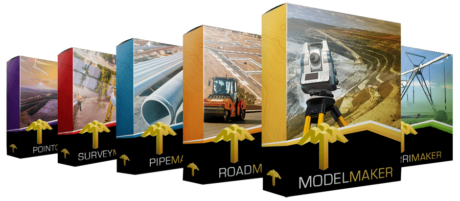
MODEL MAKER SYSTEMS SOFTWARE SOLUTIONS
Intuitive, Trusted and Affordable.
Model Maker Systems software is the trusted choice of surveyors, contractors and engineers around the globe. As an authorised dealer, we offer the full suite of solutions to streamline every project, from site planning to machine-control. We offer comprehensive support and various levels of training in the use of every aspect of the software.
Ideal for:
Technical & Land Surveying
Civil Engineering
Mining & Rehabilitation
Town Planning
Landscaping
Irrigation Design
Construction Layout
GNSS Machine Guidance
Let MMS Design help you discover how Model Maker Systems Software can elevate your workflow!
SURVEY EQUIPMENT
High Performance, Powerful, Survey Equipment.
Our survey solutions combine competitive pricing with intuitive, user-friendly design. We don’t just sell equipment—we deliver end-to-end professional solutions backed by unparalleled support.
Our team lives and breathes these products, so we truly understand your practical implementation needs. Because we use our own gear every day, we can provide hands-on expertise and responsive support whenever you need it.
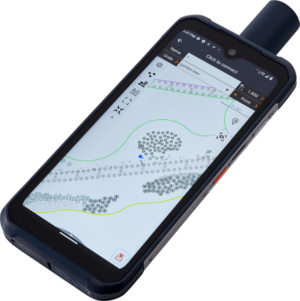
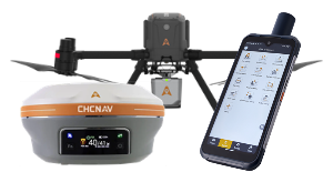
LT60H
GNSS RTK Smartphone
Rugged smartphone for accurate data collection
2-4cm with NTRIP
10-20cm Without Base corrections
YES! WE OFFER TRAINING
We offer comprehensive Model Maker Systems, IrriMaker and Landstar software training—ranging from beginner to advanced levels—for all MMS and CHCNAV Landstar software users worldwide.
Choose from group sessions in Cape Town, on-site workshops at your location, or live remote classes via your favorite online platform.
Plus, join our complimentary bi-weekly skill-up workshops to sharpen your expertise. Terms and conditions apply.
SOFTWARE TRAINING
Professional Software Courses.
Our Model Maker software training courses range from introduction to advanced and is available in Cape Town, Eastern Cape and Southern Cape.
We provide on-site training as well as workshops on request.
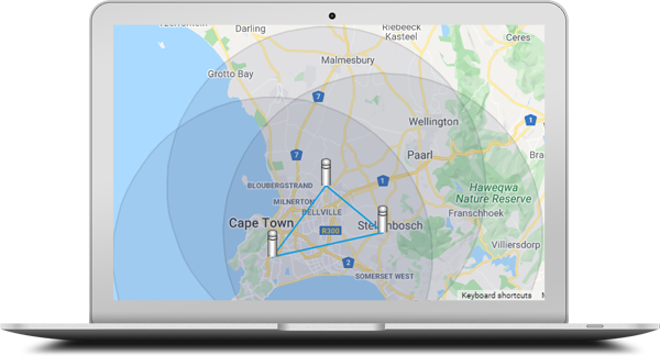
GPSNET
Our Private CORS Network of Permanent GNSSS Base Stations
Introducing our privately owned CORS network—a robust NTRIP RTK service delivering full-constellation GNSS corrections for topography, photogrammetry, construction, GIS, navigation, precision agriculture, and beyond. With both primary and backup servers in place, we guarantee 99.7% uptime, ensuring you seamless, centimeter-level accuracy whenever and wherever you need it.
Constant Updates & World-class Support Services
All of our Software and Survey Equipment are covered by world-class support.
We provide unmatched user support and training on everything we sell.
MMS Design is a proud authorised distributor of CHCNAV, and dealer of Model Maker Systems and IrriMaker software. We are also the preferred training agency for the South African Irrigation Institute for the D2 and D5 training courses
Contact Details
086 111 2783
021 975 7043
Quick Links
Home
Shop Online
Get a Quote
Software
Equipment
Training
Privacy Policy
Contact Us
Social Media
© 2025 MMS Design | All Rights Reserved | Web SEO by: DNASuperSystems